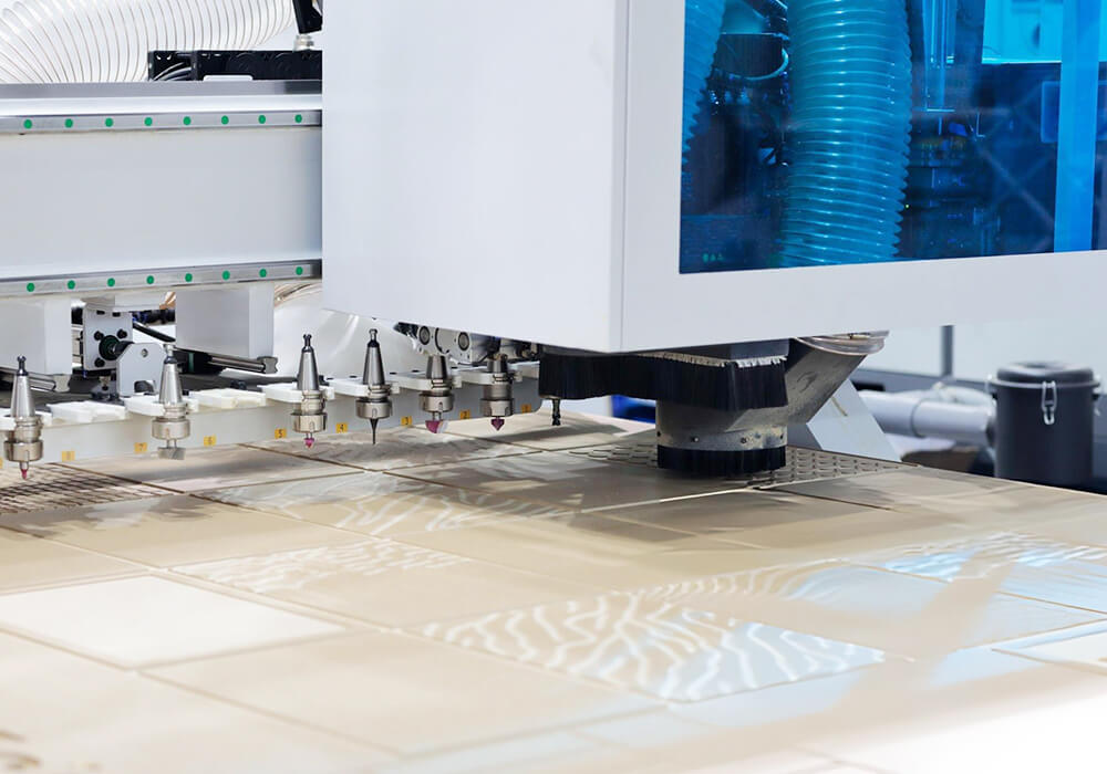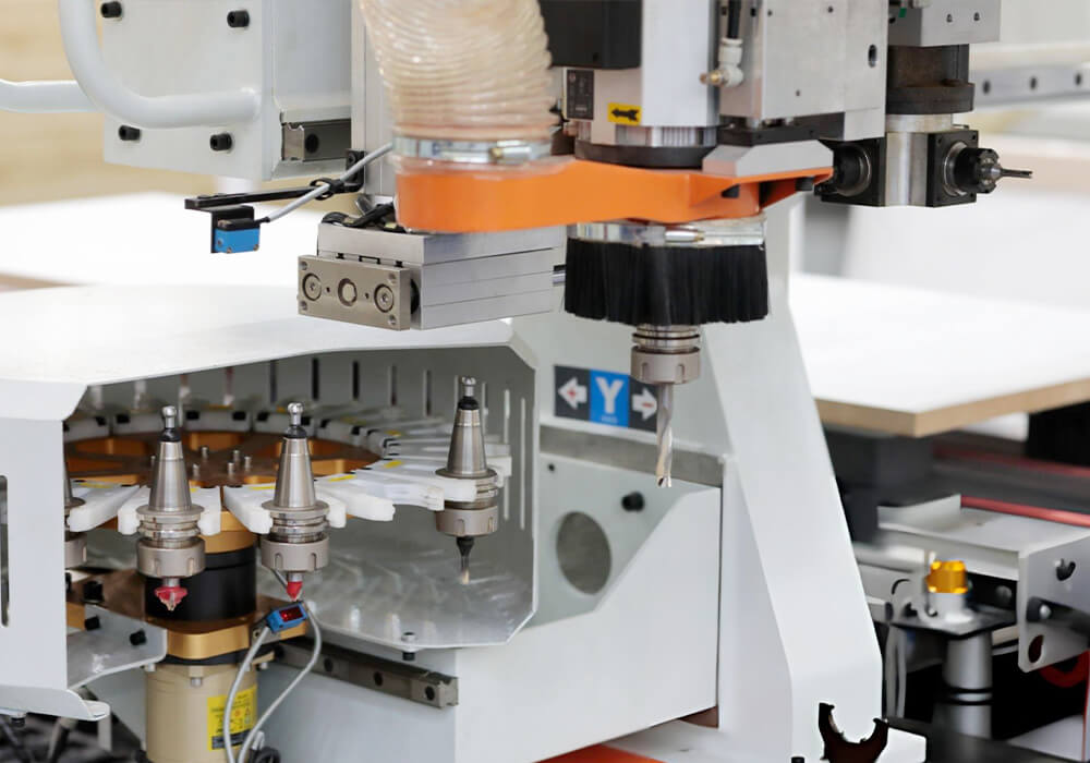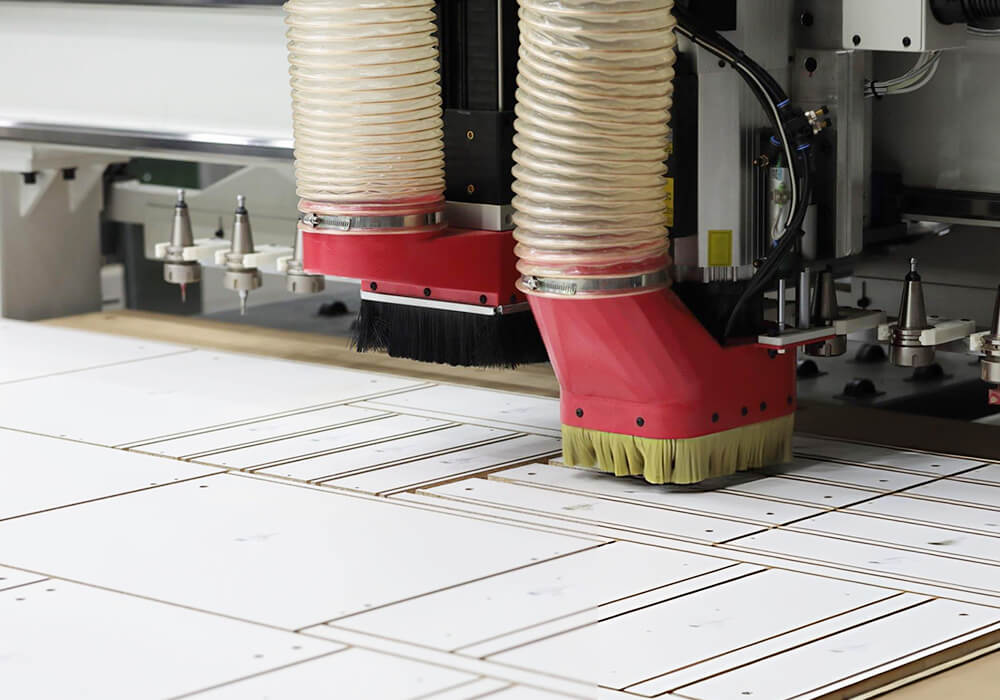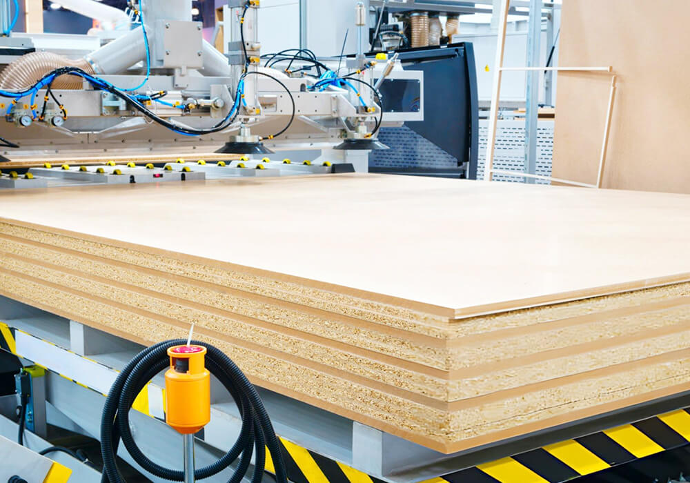
CNC Woodworking Solutions for Routing and Machining.

Plan the complete path from design data to a qualified wood component—including CAD/CAM, nesting or toolpath strategy, workholding, tooling, routing, drilling, and material flow.

Bestin helps furniture manufacturers evaluate CNC routing and machining as a production process, not as a machine specification alone. We with review your parts, materials, machining operations, software data, quality requirements and target output before recommending a machine format or automation level.

A CNC Solution Begins With the Finished Part.

Machine travel, spindle power and rapid speed do not define whether a process will produce the required component. The same CNC router can perform very differently when the part geometry, tool access, hold-down, or material changes.

We begin by defining what a qualified part means for your production.

CNC Woodworking Solutions Finished Product

1. Finished Product

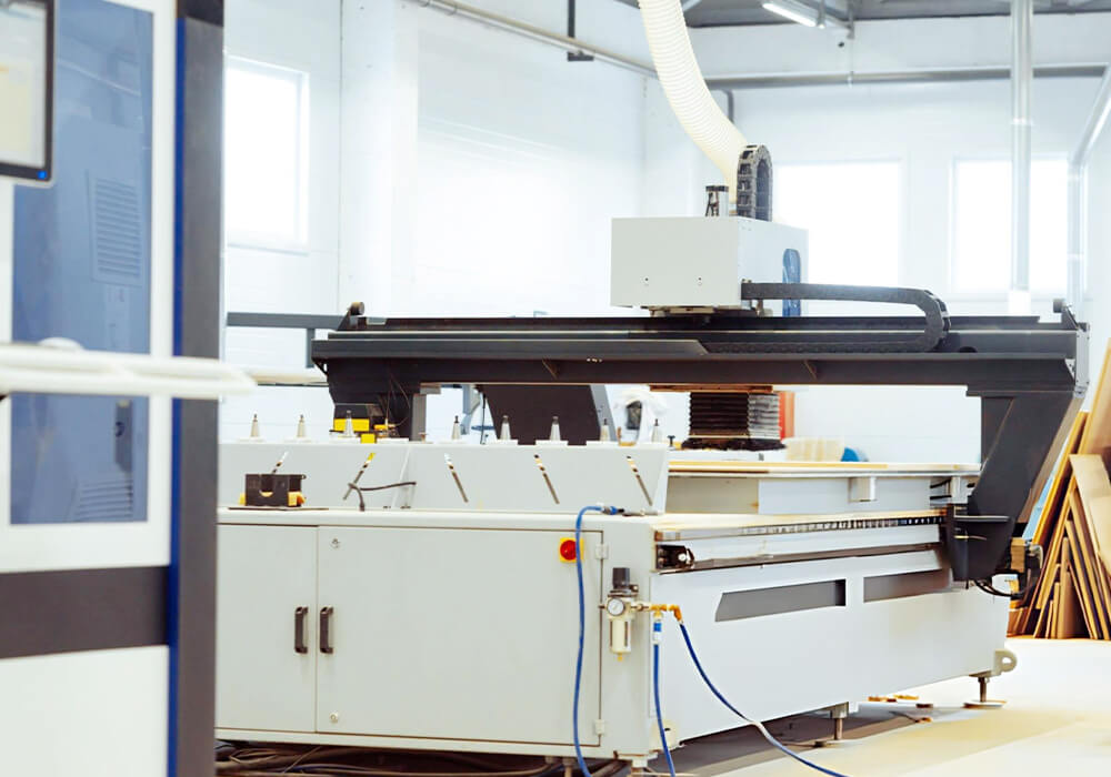
What are you manufacturing—cabinet sides, shelves, doors, solid wood components or shaped panels? We review the finished dimensions, cut-outs, pockets, grooves, holes, joints and visible surfaces.
CNC Woodworking Solutions Material and Surface

2. Material and Surface

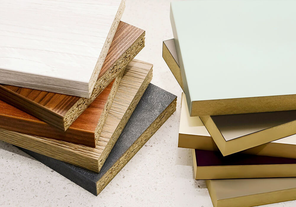
We review the material type, thickness range and so on. Panels and solid wood may require different tooling, cutting parameters and hold-down strategies.

CNC Woodworking Solutions Machining Operations

3. Machining Operations

The process may include sizing, drilling, grooving, pocketing, engraving, and so on. The sequence of operations affects tool selection, cycle time, positioning and machine format.

CNC Woodworking Solutions Machining Faces and Tool Access

4. Machining Faces and Tool Access

We identify whether features are machined from the top, side, end, underside or multiple orientations.

CNC Woodworking Solutions Quality and Acceptance

5. Quality and Acceptance

We clarify dimensional tolerance, hole position, groove width and so on. The acceptance method must be defined before a sample test is evaluated.

CNC Woodworking Solutions Production Mix and Output

6. Production Mix and Output

Batch size, number of part types, program changes and tool changes determine whether flexibility, cycle time or automation deserves more weight.

CNC Woodworking Solutions Digital Production Data

7. Digital Production Data

We review available CAD drawings, CAM files, nesting files and machine programs. File compatibility and post-processor requirements are confirmed for each application.

Woodworking Sawing And Cutting Solutions Yield and Material Flow

8. Factory Flow

The CNC process does not end when cutting stops. We review loading, unloading, labels, sorting, and transfer to edge banding, drilling, sanding, finishing or assembly.

Connect Every Step From Design Data to a Qualified Component.

A CNC machine executes the data, tooling and setup it receives. Reliable output requires the digital workflow and physical process to agree on geometry, coordinates, tools, workholding and acceptance.

Typical Panel Process: 

Part Design/CAD/CAM Import/Nesting or Toolpath Planning /Post-Processor/Material Loading/Workholding/Tool Setup and Zeroing/Routing, Drilling and Grooving/Inspection/Labeling, Sorting and Downstream Transfer

1. Part Design
The workflow begins with controlled part geometry and production information. Dimensions, hole patterns, grooves, cut-outs, machining faces, material and quantity should be defined in a form that can be checked before programming.
Design data may be imported, recreated or translated into the selected CAM environment. We review file type, geometry quality, units, layers, machining features and revision control. Compatibility is confirmed for the actual software and project.
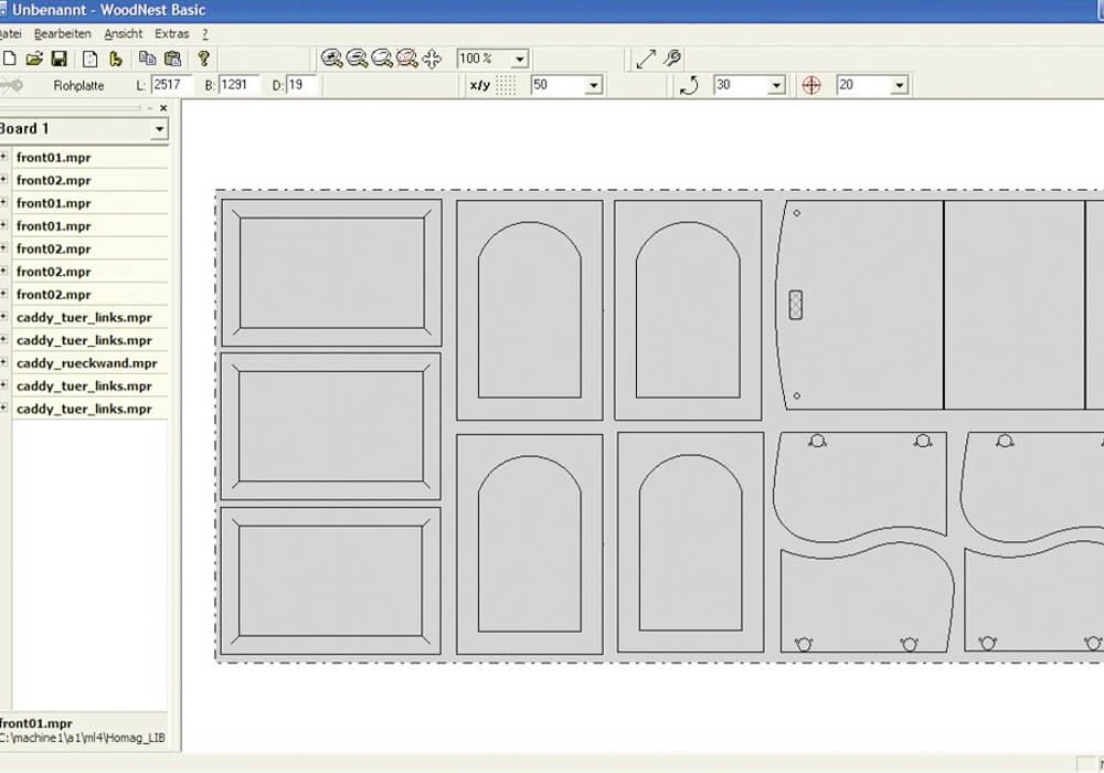
Sheet-based parts may be nested to organize components on a panel. Other work may use individual toolpaths, fixtures or pod positions. Programming should consider tool direction, lead-in and lead-out, tabs or onion-skin strategy where applicable, chip evacuation, surface quality and a safe sequence.
The post-processor translates CAM operations into instructions for the selected machine and controller. Tool numbers, coordinates, drilling cycles, spindle commands, vacuum zones, tool changes and machine-specific logic must be verified before production use.
Material may be loaded manually, with lifting assistance or through an automated system.
The workpiece must remain located and stable throughout machining. Full-sheet vacuum, zoned vacuum, pods, rails, cups, mechanical clamps or custom fixtures may be evaluated.
Tool condition, tool length, diameter, collet condition, holder cleanliness, spindle interface and coordinate zero affect the finished part. The setup method must support repeatable production, not only the first sample.
The machine performs the programmed operations in the planned sequence. Cutting parameters should match the material, tool, operation, hold-down and required edge or surface condition.
Qualified output is verified against defined criteria.
Labels or digital job information can connect the finished part with edge banding, drilling, assembly or rework.

Match the CNC Process to the Part and Production Pattern.

No single CNC format is the best answer for every furniture component. We compare the part shape, material, operation sequence, tool access, batch pattern, loading method and downstream process before selecting a path.
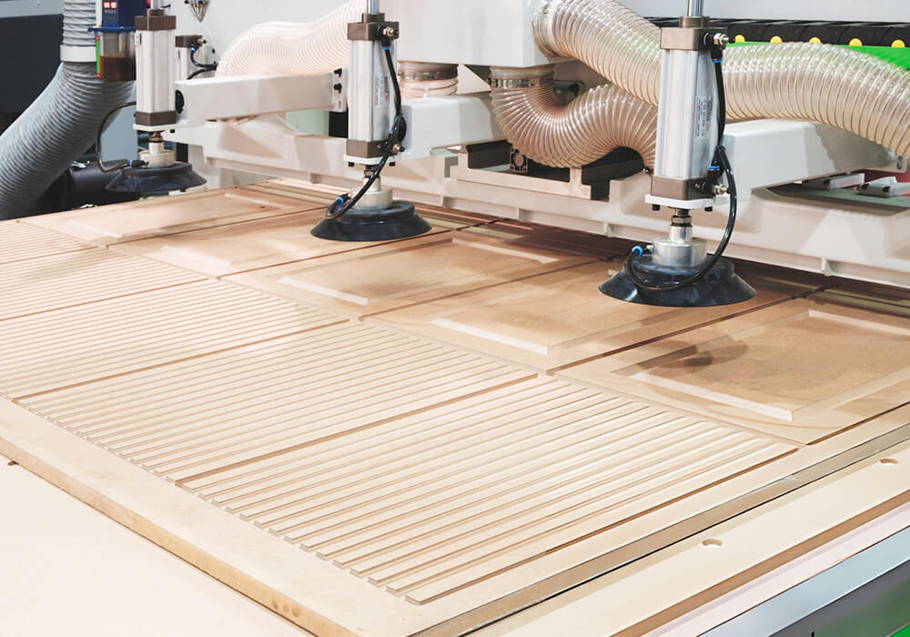
CNC Woodworking Solutions Nested-Based Panel Processing

1. Nested-Based Panel Processing

  • Typical Process:

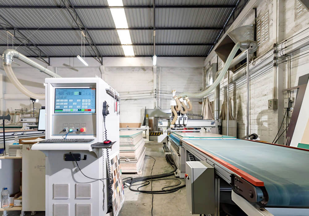
Order or cut-list data/nesting/labeling plan/sheet loading/vacuum hold-down/routing, grooving and vertical drilling/unloading/part sorting.

Confirm before selection

  • Sheet dimensions and thickness
  • Part size distribution
  • Cut-through area and vacuum leakage
  • Drill and groove requirements
  • Label and part-identification workflow
  • Real part mix and qualified output

CNC Woodworking Solutions General Flatbed Routing

2. General Flatbed Routing

  • Typical process

Part or sheet loading/vacuum or fixture setup/program selectio/routing, pocketing, grooving or drilling/inspection/unloading.

Confirm before selection:

  • Max. and min. workpiece size
  • Fixture or vacuum strategy
  • Tool count and change frequency
  • Hole patterns and drilling needs
  • Surface and edge-finish requirement
  • Manual or assisted handling

CNC Woodworking Solutions Pod-and-Rail or Point-to-Point Machining

3. Pod-and-Rail or Point-to-Point Machining

  • Typical process:

Pod or rail setup/workpiece location/ vacuum clamping/routing and drilling/repositioning if required/inspection.

Confirm before selection:

  • Part dimensions and support points
  • Pod placement and collision clearance
  • Side or end machining
  • Repositioning and registration
  • Operator changeover time

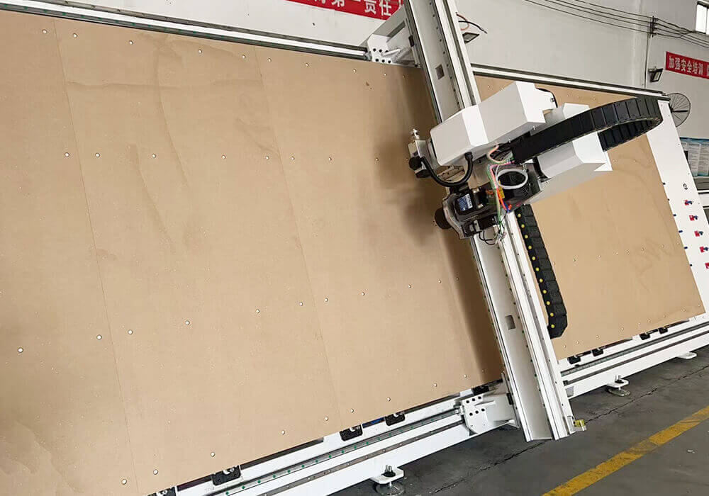
CNC Woodworking Solutions Vertical CNC Machining

4. Vertical CNC Machining

  • Typical process

Part entry/vertical location and clamping /drilling, grooving or routing /part exit/downstream transfer.

Confirm before selection

  • Supported part dimensions
  • Machining faces and edge access
  • Through-feed or return-flow requirement
  • Part identification
  • Cycle balance with upstream and downstream processes
  • Floor-space and operator route

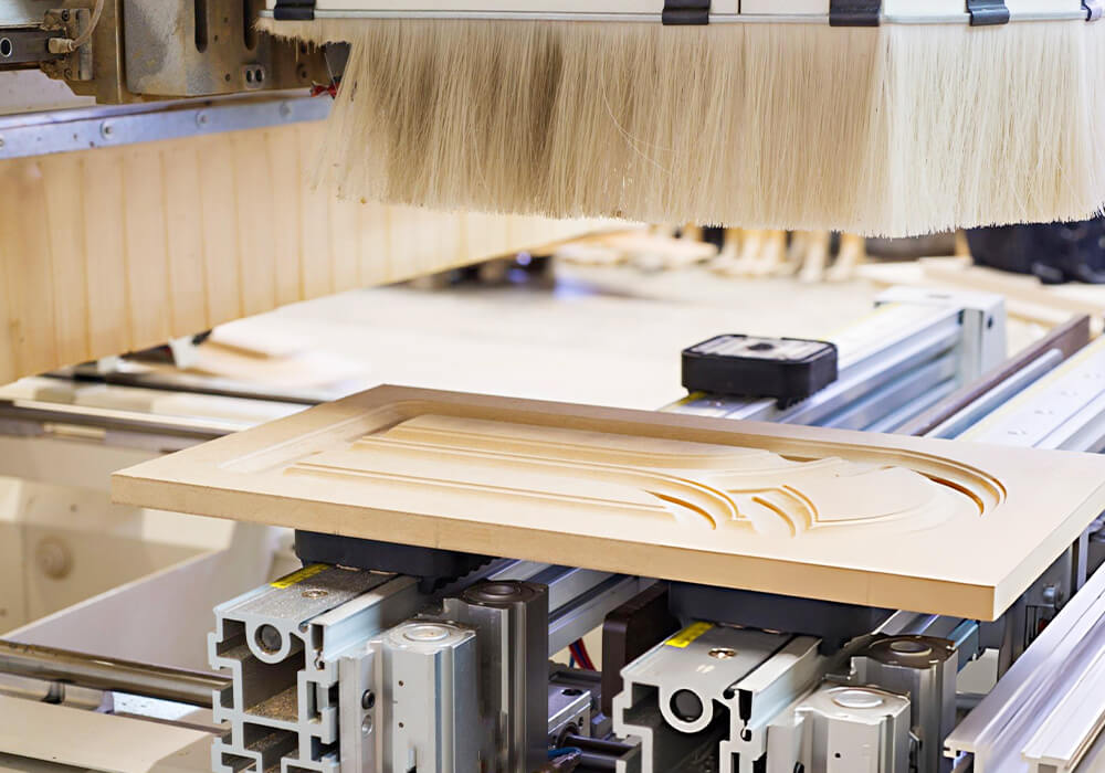
CNC Woodworking Solutions Door and Cabinet Component Machining

5. Door and Cabinet Component Machining

  • Typical process

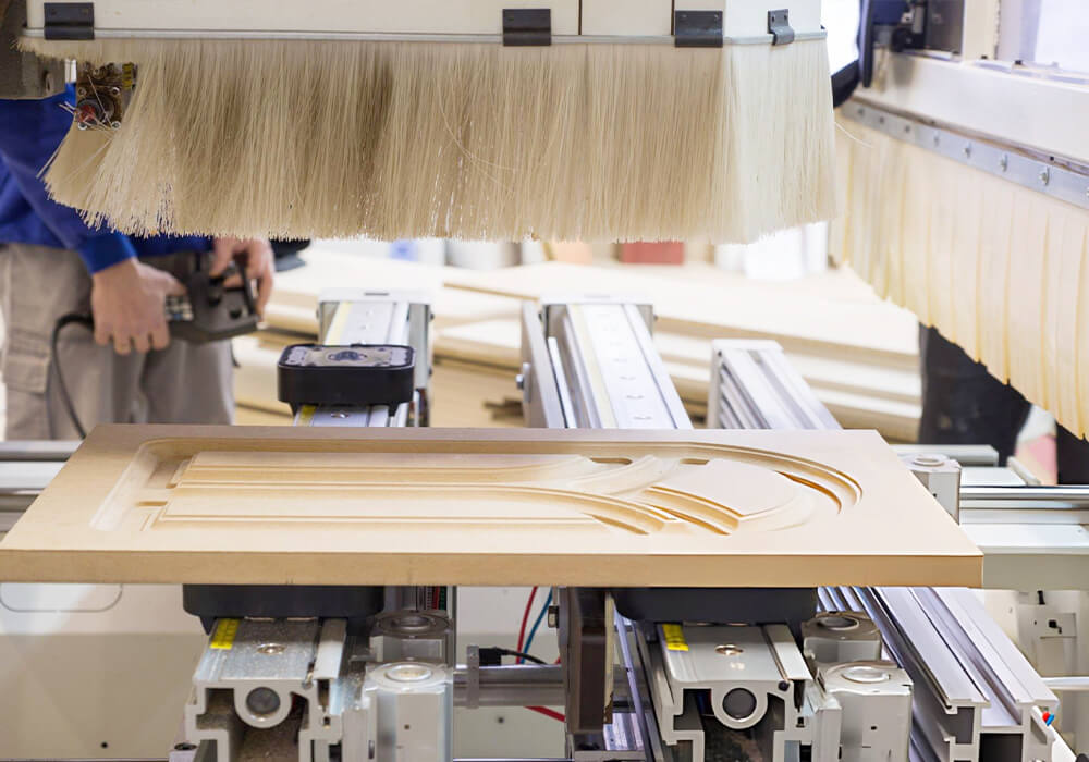
Product data/component program/ location and hold-down/drilling, grooving, routing, pocketing or joint machining/quality check/assembly preparation.

Confirm before selection

  • Product family and construction method
  • Hinge, connector and hardware patterns
  • Door profiling or pocket requirements
  • Changeover between component types
  • Downstream edge banding and assembly logic
  • Program and label control
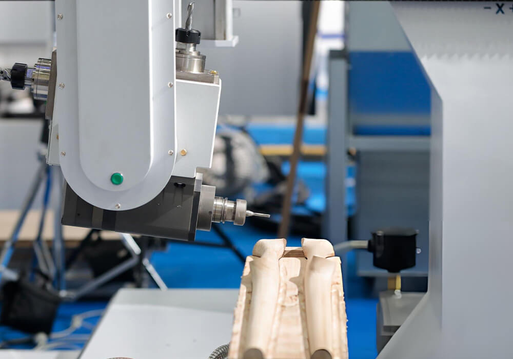
CNC Woodworking Solutions Complex Component Machining

6. Complex Component Machining

  • Typical process

3D part data/ multi-axis CAM planning/fixture and collision verification/post-processing/simulation/machining/dimensional inspection.

Confirm before selection

  • Real requirement for simultaneous or indexed axes
  • Tool access and collision envelope
  • Fixture rigidity and repeatable location
  • CAM, post-processor and simulation capability
  • Programmer and operator skills
  • Batch size and changeover economics

Our Five-Step CNC Process Review.

We use the same sequence whether the project begins with a standalone CNC router, a nesting application or a connected production cell.

1. Define the Part

We review drawings, product families, materials, dimensions, surfaces, machining faces, operations and quality requirements.

2. Map the Operations

We define the routing, drilling, grooving, pocketing, joint machining, repositioning, inspection and downstream sequence.

3. Verify Data, Tooling and Workholding

We review CAD/CAM inputs, file formats, post-processor needs, tool access, tool count, vacuum or fixture strategy and operator setup.

4. Model Production

We evaluate representative part mix, cycle elements, handling, changeovers, labels, inspection, utilization and downstream balance.

5. Test and Confirm

Where appropriate, we agree on sample material, program, configuration, measurement method and acceptance criteria before evaluating results.

Choose the Automation Level From the Production Constraint.

Automation should solve a defined problem such as repetitive handling, identification errors, unstable flow, operator dependence or insufficient qualified output. It should not be added without checking part variety, exceptions, maintenance skills and downstream balance.
CNC Woodworking Solutions Standalone CNC Machine

Standalone CNC Machine

  • Often Evaluated For:

Flexible production, lower or variable volume, frequent process changes and factories where operators manage loading, unloading and sorting.

Typical Scope

  • Manual material selection
  • Manual or assisted loading
  • Local program selection
  • CNC machining
  • Manual inspection and unloading

CNC Woodworking Solutions CNC With Assisted Handling

CNC With Assisted Handling

  • Often Evaluated For

Processes where lifting, part return, panel alignment, labeling or unloading is the main constraint.

Typical Scope

  • Lifting assistance or loading table
  • Positioning support
  • Labeling or part identification
  • Manual exception handling

Woodworking Sawing And Cutting Solutions Connected Cutting Cell

Connected CNC Production Cell

Often Evaluated For:

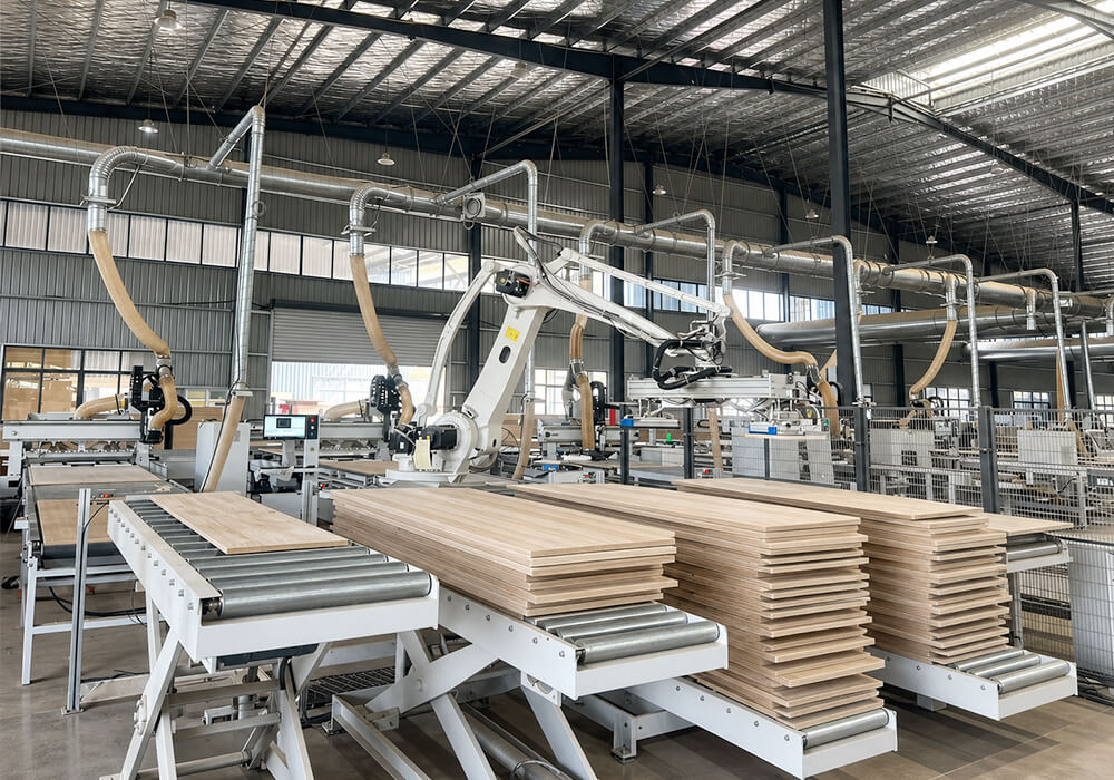
Repeatable digital order flow, higher volume, reduced manual handling and coordinated labeling, loading, machining and sorting.

Typical Scope

  • Order or production data
  • Material storage or loading
  • Program and label generation
  • CNC machining
  • Unloading and sorting
  • Downstream data or material transfer

Explore CNC Machinery and Production Paths.

Once the process requirement is clear, compare only the machine categories and system paths that match the application.

CNC Wood Routers

For flexible flatbed routing, profiling, pocketing, grooving and selected drilling applications.

CNC Machining Centers

For component machining where tool access, fixtures, pods or multiple operations are central.

CNC Nesting Machines

For sheet-based cabinet and panel-furniture part production driven by nesting data.

Vertical CNC Routers

For confirmed panel-machining applications where vertical processing or factory flow may be appropriate.

CNC Nesting Production Cell

For projects connecting order data, loading, nesting, machining, labeling, unloading and sorting.

Tell Us What You Need to Edge Band.

Send your product, material, process and output requirements. We will help you identify a relevant machine category, confirmed model or production-solution pathway.

wood moulders for sale

FAQ About CNC Woodworking Solutions.

What is the difference between a CNC router and a CNC machining center?
A CNC router commonly describes a machine used for routing, profiling, grooving, pocketing and selected drilling on a flat work area. A CNC machining center may include a broader combination of tools, drilling units, workholding systems, edge access or multiple-axis functions. Product terminology varies by manufacturer, so the actual operations, workholding and tool access should be compared.
A nesting machine is configured around full-sheet processing, nested layouts, vacuum hold-down and repeated panel-component flow. A general CNC router may support a wider mix of sheet, component, fixture and shaped-part work. The distinction depends on the table, drilling and tool configuration, software, handling and intended workflow.
Nesting is often evaluated when varied components, shaped parts and combined routing or grooving are important. A panel-saw-based process is often evaluated for repeated rectangular cutting, stack opportunities and a separate drilling workflow. The correct comparison uses the real cut list, part mix, quality, yield, cycle, labor and downstream process.
Start with the machining faces, angles, tool approaches and number of setups required by the part. Three-axis machines commonly address top-face operations. Additional axes may support angled, rotary or complex multi-direction machining, depending on the architecture. More axes also add programming, post-processing, fixture, collision and skill requirements, so axis count should not be selected in isolation.
A vacuum table is often evaluated for full sheets and broad flat support. Pod-and-rail systems are often evaluated for finished-size parts, underside clearance and selected edge access. Part size, porosity, machining faces, cut-through area, tool clearance, setup time and batch pattern determine the suitable workholding concept.