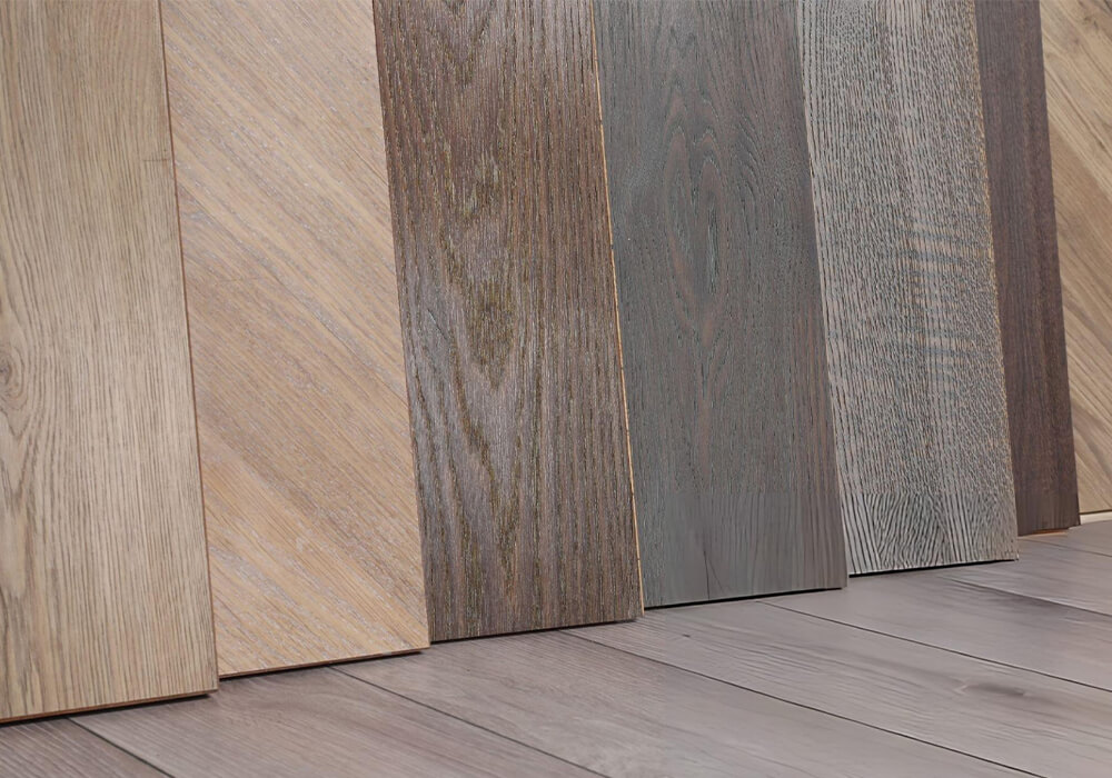
Wood Sanding Solutions for Calibration and Surface Preparation.

BESTIN supplies sanding and calibration machine for panels, cabinet doors, profiles and solid wood components.

Send us the material, incoming defects, stock-removal allowance, required finish and output target. We will help you choose the sanding stages, contact method and machine configuration for the work.

Define the Required Surface Before Selecting the Sander.
Working width and motor power do not define the finished result. Sanding also depends on the material, abrasive, contact pressure, feed, stock allowance and incoming condition.
Wood Sanding Solutions Finished Product

1. Finished Product

What are you making—cabinet panels, doors, tabletops, solid wood components or mouldings? Identify the visible surfaces and the next operation.
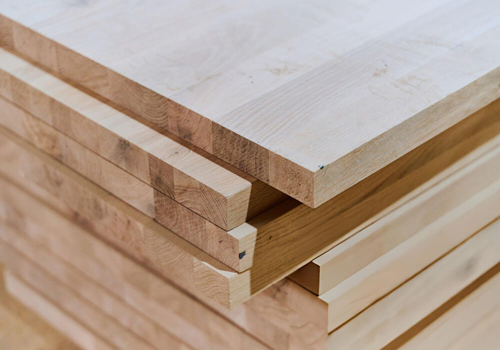
Wood Sanding Solutions Material and Surface Layer

2. Material and Surface Layer

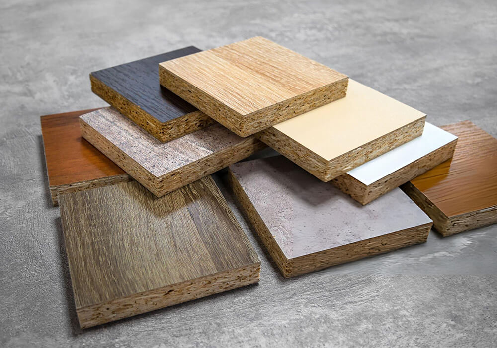
Provide the substrate or wood species, face material, veneer thickness, coating system and any layer that must not be sanded through.
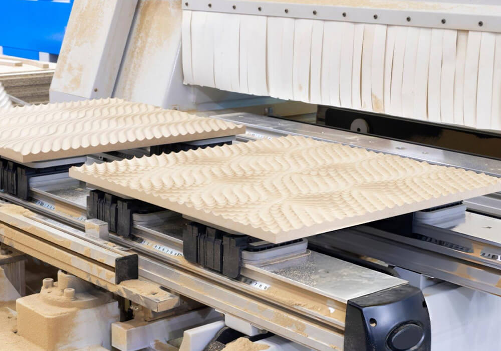
Wood Sanding Solutions Geometry and Surfaces

3. Geometry and Surfaces

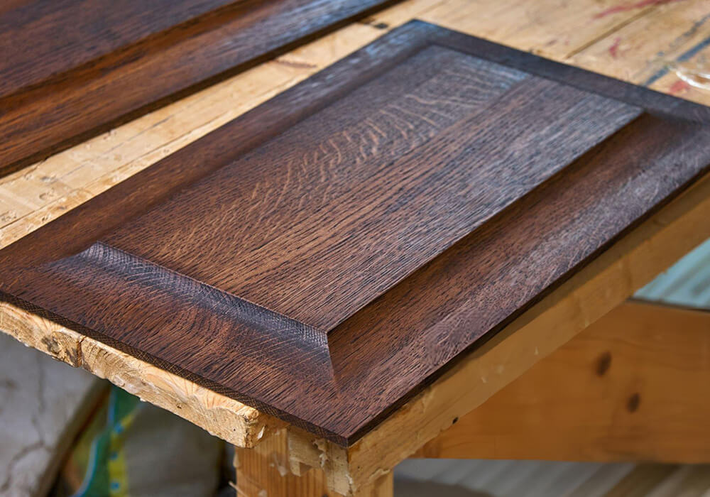
Tell us whether the part is flat, framed, profiled, grooved, carved or three-dimensional. Mark the faces, edges and recesses that need sanding.
Wood Sanding Solutions Required Stock Removal

4. Required Stock Removal

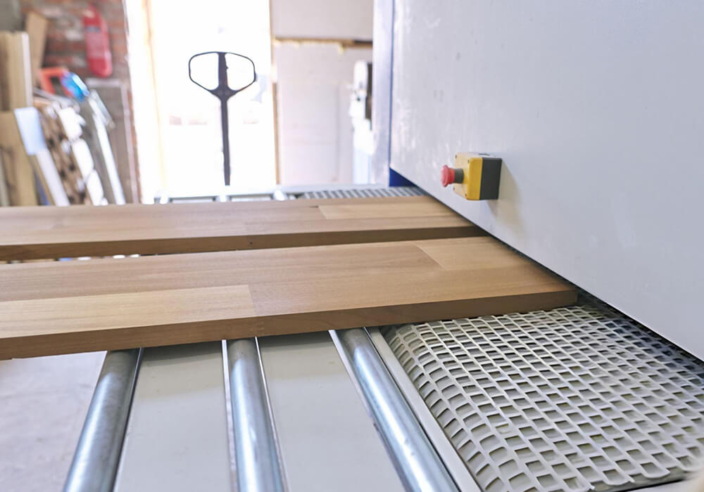
Confirm the incoming thickness, target thickness, defect depth and minimum remaining veneer or coating. State whether material can be removed from one face or both.
Wood Sanding Solutions Production Mix and Output

5. Production Mix and Output

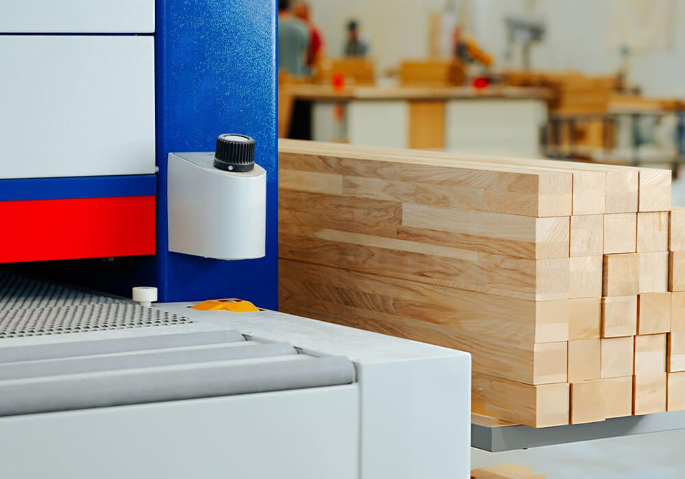
Share the part sizes, batch quantities, material changes, abrasive changes, shifts and acceptable parts required per shift.
Wood Sanding Solutions Factory and Dust Extraction

6. Factory and Dust Extraction

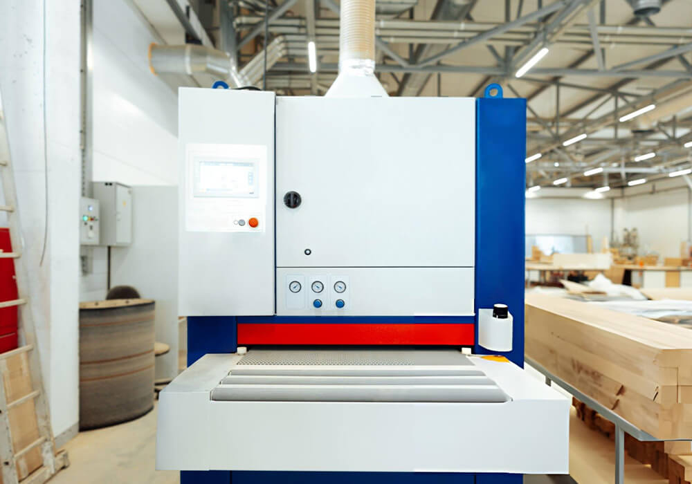
Provide the loading and unloading method, return flow, available floor space, existing dust-extraction capacity and connection to the next process.

Give Every Sanding Stage a Defined Job.

Each stage should remove a known defect and leave a predictable surface for the next abrasive or finishing process.

Process Flow:

Incoming Material Inspection/Sanding-Allowance Allocation /Thickness Calibration/Coarse Sanding/Intermediate Sanding/Edge or Profile Sanding/ Fine or Sealer Sanding/Cleaning and Dust Removal/Surface Inspection and Downstream Transfer

1. Inspect the incoming part
Measure thickness variation and identify cutter marks, glue lines, fibers, dents, coating defects and other areas that affect the sanding plan.
Decide which defects must be removed, how much material is available and whether removal should be split between faces or operations.
Calibration reduces thickness variation and establishes a more consistent dimension. Workpiece support, reference face, abrasive, contact roller and pressure must suit the material and allowance.
The coarse stage removes the agreed incoming marks without creating deeper scratches that later stages cannot remove efficiently.
Intermediate abrasives remove the previous scratch pattern. The number of stages depends on the starting condition, material and required final surface.
Belts, discs, wheels, brushes or profile tools can reach edges, grooves and contours. The contact method should remove marks without rounding features that must remain sharp.
Fine and sealer sanding require light, controlled contact to avoid breakthrough, excessive edge rounding and an uneven surface.
Remove loose dust before checking the part under the agreed light and measurement conditions. Accepted parts can then move to coating, laminating, bonding or assembly.
The part is compared with defined measurements, defect limits and, where appropriate, an approved sample under specified light. Accepted parts move to coating, laminating, bonding, assembly or another confirmed process.

Choose the Sanding Path From the Material, Geometry and Finish.
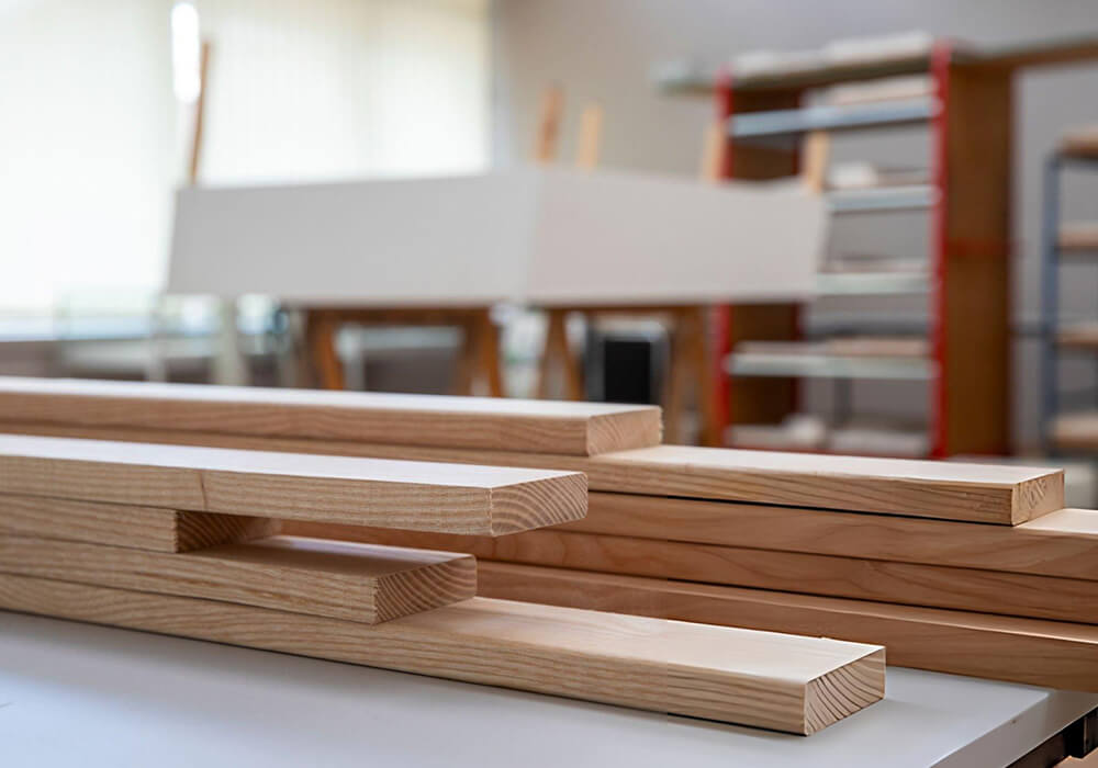
Different components require different contact methods. We compare the part and finish requirement before deciding how many sanding heads or machine types are needed.
Wood Sanding Solutions Flat Panel and Solid Wood Calibration

1. Flat Panel and Solid Wood Calibration

  • Best Suit For:

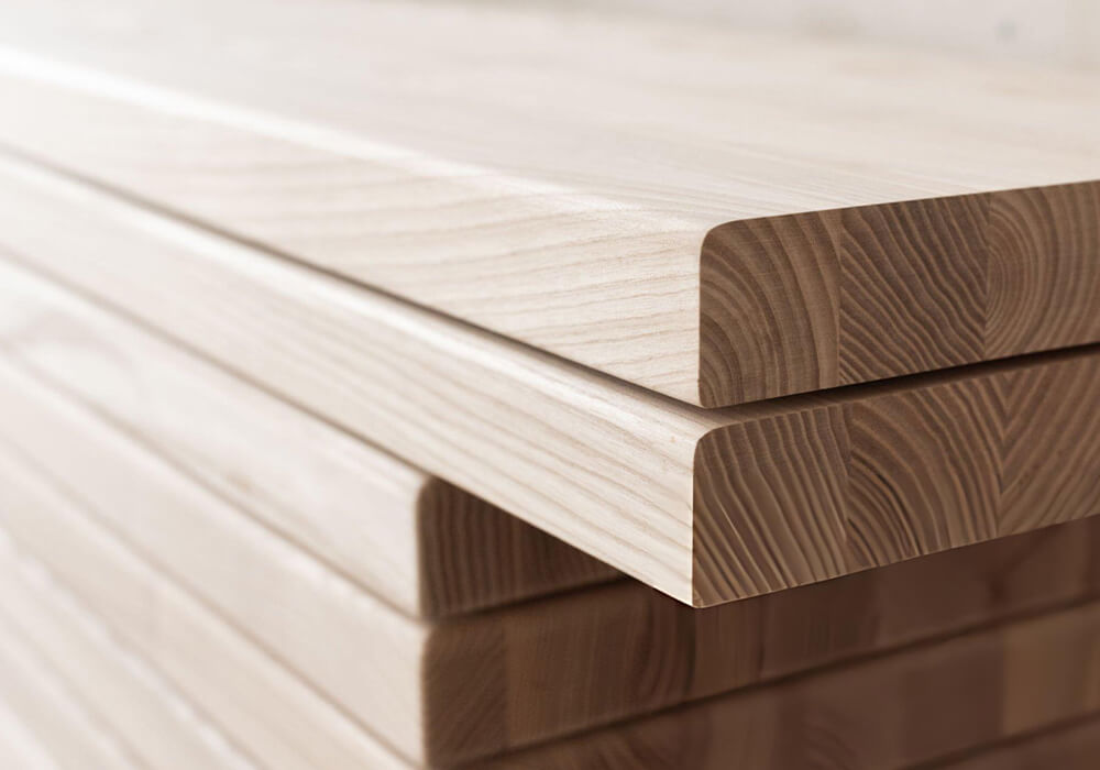
For solid wood panels, glued panels, doors, tabletops, MDF and other flat materials that need thickness control or leveling

Confirm before selection

  • Incoming and target thickness
  • Thickness variation across the part and batch
  • Material hardness and moisture condition
  • One-face or two-face processing
  • Required stock removal
  • Surface condition after calibration
  • Min. part size and stability

Wood Sanding Solutions Raw and Veneered Panel Sanding

2. Raw and Veneered Panel Sanding

  • Best Suit For:

For MDF, particleboard, plywood and veneered panels that need pre-sanding, fine sanding or preparation for coating or laminating.

Confirm before selection

  • Substrate and face layer
  • Veneer or coating thickness
  • Glue lines and local high points
  • Panel flatness
  • Contact pressure
  • Accepted scratch and fiber condition
  • Breakthrough limit

Wood Sanding Solutions CNC-Machined and Cabinet Door Preparation

3. CNC-Machined and Cabinet Door Preparation

  • Often Evaluated For

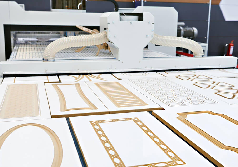
For routed MDF doors, cabinet fronts and decorative panels with cutter marks, grooves, corners and profiles.

Confirm before selection

  • CNC tool-mark depth and direction
  • Groove and profile geometry
  • Sharp features that must be retained
  • Min. part size
  • Brush, disc or belt reach
  • Part hold-down
  • Final paint or coating requirement

Wood Sanding Solutions Edge and Profile Sanding

4. Edge and Profile Sanding

  • Best Suit For:

Straight edges, profiled edges, door frames, mouldings, shelves, furniture components and parts that require controlled edge preparation.

Confirm before selection

  • Edge material and geometry
  • Straight, bevel, radius or custom profile
  • Required removal
  • Profile retention
  • Workpiece length and support
  • Contact sequence
  • Upstream machining quality

Wood Sanding Solutions Lacquer and Sealer Sanding

5. Lacquer and Sealer Sanding

  • Often Evaluated For:

For sanding between compatible coating stages to remove nibs, raised fibers and minor irregularities without sanding through the film.

Confirm before selection

  • Coating system and cure condition
  • Film thickness and variation
  • Required contact sensitivity
  • Edge and profile risk
  • Abrasive loading
  • Dust cleaning
  • Approved finish sample

Wood Sanding Solutions Brushing and Structuring

6. Brushing and Structuring

  • Best Suit For:

Solid wood, panels or components that require grain enhancement, fiber removal, light texturing or another controlled decorative surface effect.

Confirm before selection

  • Required visual and tactile effect
  • Species, grain and surface layer
  • Brush material and direction
  • Pressure, speed and number of stages
  • Repeatability across natural material variation
  • Downstream coating or oil process

Our Five-Step Sanding Process Review.

We use the same sequence whether the project begins with one sanding machine, a difficult surface defect or a connected sanding line.

1. Define the Surface

We check the product, material, incoming condition, geometry, visible areas, next finish and acceptance sample.

2. Allocate the Sanding Allowance

We confirm the target thickness, defect depth, remaining surface layer and the purpose of each sanding stage.

3. Select the Contact and Abrasive Strategy

We compare contact rollers, pads, belts, discs, brushes and profile units, then identify the variables that need a sample test.

4. Model Production and Extraction

The review includes handling, return flow, changeovers, abrasive replacement, cleaning, inspection, dust extraction and transfer to the next process.

5. Test and Confirm

For project-specific tests, the material, defect, machine setup, abrasive sequence, measurement method and acceptance criteria are recorded in advance.

Explore the Sanding Path That Matches the Application.

Once the surface requirement is clear, compare only the machine categories and connected processes that fit the material, geometry and production plan.

Wide Belt Sanders

For confirmed flat-panel, solid wood, calibration, intermediate and fine-sanding applications.

Brush Sanders

For confirmed CNC-mark, fiber, groove, profile and flexible-contact applications.

Calibration Sanders

For projects where controlled thickness and stock-removal planning are central.

Edge and Profile Sanders

For straight edges, shaped edges, frames, mouldings and defined profile preparation.

Sanding & Calibration Line

For projects connecting material handling, calibration, sanding, cleaning, inspection and downstream transfer.

Finishing &Coating

For coating application, film build, flash-off, drying and curing after an accepted surface has been prepared.

Tell Us What the Surface Looks Like Now—and What It Must Become.

Send the material, defect, finish and production information you already have. We will use it to identify the process questions, suitable sanding paths and any information still needed before a configuration is prepared.
wood moulders for sale

FAQ About Wood Sanding Solutions.

What is the difference between calibration and sanding?
Calibration controls thickness or establishes a more consistent dimension through defined material removal. Sanding controls the surface by removing or refining marks, fibers and irregularities. One machine may combine both operations for suitable applications, but the allowance and acceptance standard should be defined separately.
A wide belt sander and a thickness planer use different cutting actions and are selected from different removal and finish requirements. A sander may perform controlled calibration for suitable materials, but heavy removal can affect cycle, abrasive life and surface behavior. Compare the incoming condition, allowance, target finish and output before replacing one process with another.
A wide belt sander is commonly evaluated for flat surfaces, calibration and belt-based finish stages. A brush sander is commonly evaluated for fibers, CNC marks, profiles, grooves and flexible contact. Some products require both paths, while others require only one. The part geometry and accepted surface determine the choice.
Start with the material, incoming defect and allowable stock removal. The first abrasive should remove the defined defect, and each later stage should remove the previous scratch condition until the approved final surface is reached. Confirm the sequence with representative parts.
First identify the mark depth, direction and affected geometry. The CNC tool and machining process should be reviewed before sanding. Brush, disc, profile or other flexible-contact units may then be evaluated for the remaining marks without removing required details. Confirm the result with the real door profile and paint process.
Some multi-unit configurations can combine calibration, intermediate and fine sanding for suitable parts. Capability depends on the units, abrasive sequence, required removal, material, number of faces, accepted finish and line speed. Bestin confirms the configuration for each application.
The coating system, cure condition, film thickness, defect, edge and profile geometry, accepted surface and dust-removal method must be defined. A representative coated sample should be tested. Final coating quality also depends on application, environment, drying and curing outside the sanding process.
A sample test may be arranged when representative material, incoming defect, target surface, abrasive, configuration, measurement method and acceptance criteria can be agreed. The result applies only to the recorded test conditions.